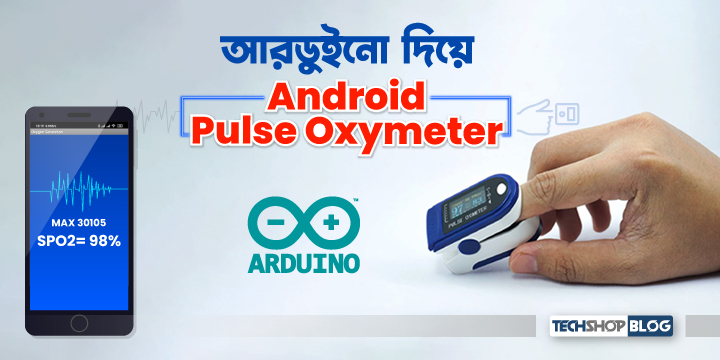
পালস অক্সিমিটার তৈরী করা আমরা ইতোমধ্যে দেখেছি এই টিউটোরিয়ালে। এবার আমরা যে পালস অক্সিমিটারটি তৈরী করব সেটির ডিসপ্লে হচ্ছে আমাদের মোবাইল ফোন। আমরা এমন একটি মোবাইল অ্যাপ তৈরী করব যা অক্সিমিটারের রিডিং মোবাইল ফোনে দেখাবে।
/wp:paragraph wp:table| প্রয়োজনীয় যন্ত্রপাতি | পরিমান | লিংক |
| Arduino Mega-2560(China) | 1 | এখানে ক্লিক করুন |
| SparkFun Particle Sensor Breakout – MAX30105 | 1 | এখানে ক্লিক করুন |
| Mini Breadboard | 1 | এখানে ক্লিক করুন |
| Male to male jumpers | 4 | এখানে ক্লিক করুন |
| Wireless programming and communication shield | 1 | এখানে ক্লিক করুন |
| 2S Li-Ion Battery with Charger | 1 | এখানে ক্লিক করুন |
| Rubber band | 1 |
সার্কিটঃ
/wp:paragraph wp:paragraphপ্রথমে মোবাইলের সাথে wireless programming shield কে মোবাইলের সাথে পেয়ার করিয়ে নিতে হবে। পেয়ার করতে যেকোনো সমস্যার সমাধানের জন্য এই ম্যানুয়ালটি দেখতে হবে।
/wp:paragraph wp:paragraph/wp:paragraph wp:paragraph
প্রথমে রাবার ব্যান্ডটিকে পার্টিকেল সেন্সরের সাথে সংযুক্ত করি।
/wp:paragraph wp:image {“id”:77919,”sizeSlug”:”large”}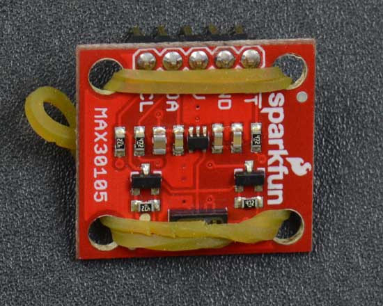
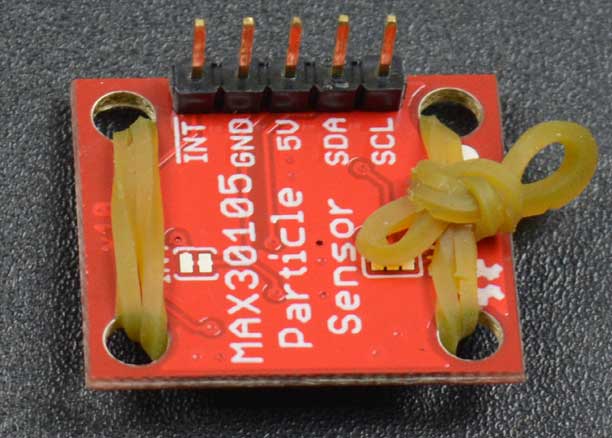
আরডুইনোর উপরে Wireless programming and communication shield কে বসাই। পার্টিকেল সেন্সর ও আরডুইনোর মধ্যে নিচের কানেকশনটি সম্পন্ন করি।
/wp:paragraphStartFragment
wp:table| Arduino UNO-R3 | SparkFun Particle Sensor Breakout – MAX30105 |
| VCC | 5V |
| GND | GND |
| SDA | A4 |
| SCL | A5 |
ব্যাটারি দিয়ে আরডুইনোকে পাওয়ার আপ করে সার্কিট সম্পন্ন করি।
/wp:paragraph wp:image {“id”:77934,”sizeSlug”:”large”}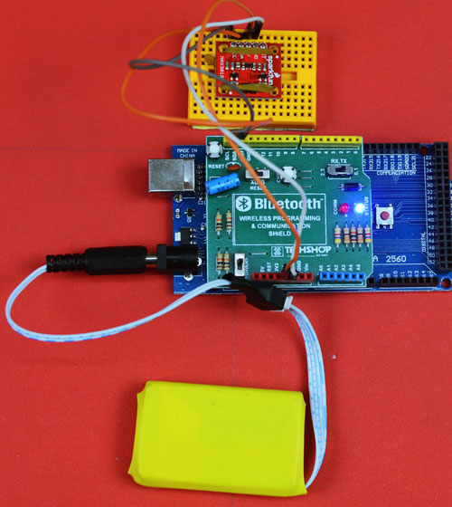
কোডঃ
/wp:paragraph wp:paragraphপ্রথমে এই লাইব্রেরিটি ডাউনলোড করি এবং ইন্সটল করি। তারপর নিচের কোডটি আরডুইনোতে আপলোড করি।
/wp:paragraph wp:code#include <Wire.h>
#include "MAX30105.h"
#include "spo2_algorithm.h"
const byte RATE_SIZE = 4; //Increase this for more averaging. 4 is good.
byte rates[RATE_SIZE]; //Array of heart rates
MAX30105 particleSensor;
#define MAX_BRIGHTNESS 255
#if defined(__AVR_ATmega328P__) || defined(__AVR_ATmega168__)
//Arduino Uno doesn't have enough SRAM to store 100 samples of IR led data and red led data in 32-bit format
//To solve this problem, 16-bit MSB of the sampled data will be truncated. Samples become 16-bit data.
uint16_t irBuffer[100]; //infrared LED sensor data
uint16_t redBuffer[100]; //red LED sensor data
#else
uint32_t irBuffer[100]; //infrared LED sensor data
uint32_t redBuffer[100]; //red LED sensor data
#endif
int32_t bufferLength; //data length
int32_t spo2; //SPO2 value
int8_t validSPO2; //indicator to show if the SPO2 calculation is valid
int32_t heartRate; //heart rate value
int8_t validHeartRate; //indicator to show if the heart rate calculation is valid
byte readLED = 13; //Blinks with each data read
void setup()
{
Serial.begin(115200); // initialize serial communication at 115200 bits per second:
pinMode(readLED, OUTPUT);
// Initialize sensor
if (!particleSensor.begin(Wire, I2C_SPEED_FAST)) //Use default I2C port, 400kHz speed
{
Serial.println(F("MAX30105 was not found. Please check wiring/power."));
while (1);
}
while (Serial.available() == 0) ; //wait until user presses a key
Serial.read();
byte ledBrightness = 60; //Options: 0=Off to 255=50mA
byte sampleAverage = 4; //Options: 1, 2, 4, 8, 16, 32
byte ledMode = 2; //Options: 1 = Red only, 2 = Red + IR, 3 = Red + IR + Green
byte sampleRate = 100; //Options: 50, 100, 200, 400, 800, 1000, 1600, 3200
int pulseWidth = 411; //Options: 69, 118, 215, 411
int adcRange = 4096; //Options: 2048, 4096, 8192, 16384
particleSensor.setup(ledBrightness, sampleAverage, ledMode, sampleRate, pulseWidth, adcRange); //Configure sensor with these settings
}
void loop()
{
bufferLength = 100; //buffer length of 100 stores 4 seconds of samples running at 25sps
//read the first 100 samples, and determine the signal range
for (byte i = 0 ; i < bufferLength ; i++)
{
while (particleSensor.available() == false) //do we have new data?
particleSensor.check(); //Check the sensor for new data
redBuffer[i] = particleSensor.getRed();
irBuffer[i] = particleSensor.getIR();
particleSensor.nextSample(); //We're finished with this sample so move to next sample
}
//calculate heart rate and SpO2 after first 100 samples (first 4 seconds of samples)
maxim_heart_rate_and_oxygen_saturation(irBuffer, bufferLength, redBuffer, &spo2, &validSPO2, &heartRate, &validHeartRate);
//Continuously taking samples from MAX30102. Heart rate and SpO2 are calculated every 1 second
while (1)
{
//dumping the first 25 sets of samples in the memory and shift the last 75 sets of samples to the top
for (byte i = 25; i < 100; i++)
{
redBuffer[i - 25] = redBuffer[i];
irBuffer[i - 25] = irBuffer[i];
}
//take 25 sets of samples before calculating the heart rate.
for (byte i = 75; i < 100; i++)
{
while (particleSensor.available() == false) //do we have new data?
particleSensor.check(); //Check the sensor for new data
digitalWrite(readLED, !digitalRead(readLED)); //Blink onboard LED with every data read
redBuffer[i] = particleSensor.getRed();
irBuffer[i] = particleSensor.getIR();
particleSensor.nextSample(); //We're finished with this sample so move to next sample
//send samples and calculation result to terminal program through UART
if(spo2==-999)
{
Serial.print(" ");
Serial.print("?");
Serial.println(" ");
}
else{
Serial.print(" ");
Serial.print("SPO2=");
Serial.print(spo2,DEC);
Serial.println("%");
Serial.println(" ");
}
}
//After gathering 25 new samples recalculate HR and SP02
maxim_heart_rate_and_oxygen_saturation(irBuffer, bufferLength, redBuffer, &spo2, &validSPO2, &heartRate, &validHeartRate);
}
}
অ্যাপ তৈরীঃ
/wp:paragraph wp:paragraphঅ্যান্ডয়েড অ্যাপটি তৈরী করতে আমরা ব্যবহার করব MIT app inventor । এটি সম্পর্কে আগের দুটি টিউটোরিয়ালে ইতোমধ্যে বিশদ আলোচনা করা হয়েছে।
/wp:paragraph wp:paragraphডিজাইনার অংশঃ
/wp:paragraph wp:paragraphঅ্যাপের স্ক্রিনটি দেখতে হবে এরকমঃ
/wp:paragraph wp:image {“id”:77886,”sizeSlug”:”large”}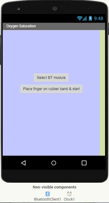
স্ক্রিনের কম্পোনেন্টগুলো নিম্নরুপ।
/wp:paragraph wp:image {“id”:77887,”sizeSlug”:”large”}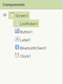
Screen 1: স্ক্রিনের টাইটেল হচ্ছে Oxygen Saturation. ইচ্ছে হলে অন্যকোনো নামও দেওয়া যেতে পারে।
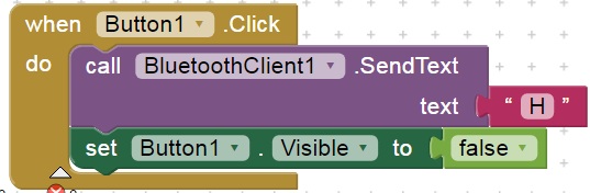
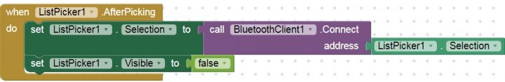
/wp:paragraph wp:paragraphListpicker 1: এটি হচ্ছে ব্লুটুথ মডিউল সিলেকশনের বাটন। আমরা লিস্টপিকারের টেক্সটের জায়গায় লিখেছি ‘Select BT module’।
/wp:paragraph wp:paragraphButton 1: এটি হচ্ছে ‘Place finger on rubber band and start’ লেখা বাটনটি। এটি প্রেস করার পরই আমরা আরডুইনো থেকে ডেটা রিসিভ করতে শুরু করব।
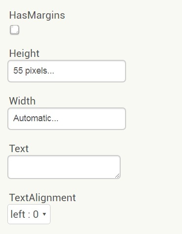
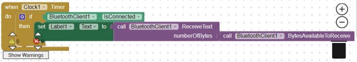
/wp:paragraph wp:paragraphLabel 1: এইখানে আরডুইনো থেকে প্রাপ্ত ডেটা অর্থ্যাৎ, অক্সিজেন স্যাচুরেশন দেখা যাবে। প্রপার্টিজে গিয়ে Label 1 এর প্যারামিটারগুলো এভাবে সেট করতে হবেঃ
/wp:paragraph wp:image {“id”:77904,”sizeSlug”:”large”}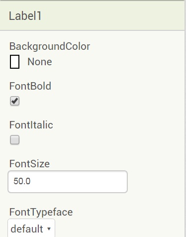
/wp:paragraph wp:image {“id”:77907,”sizeSlug”:”large”}
ব্লক অংশঃ
/wp:paragraph wp:image {“align”:”wide”,”id”:77888,”sizeSlug”:”large”}
/wp:paragraph wp:paragraph {“fontSize”:”medium”}
তৈরী অ্যাপ ডাউনলোড করাঃ
/wp:paragraph wp:image {“id”:77909,”sizeSlug”:”large”}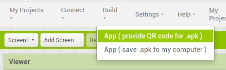
এরকম একটি কিউআর কোড স্ক্রিনে দেখা যাবে।
/wp:paragraph wp:image {“id”:77911,”sizeSlug”:”large”}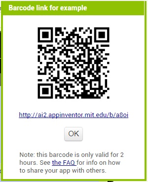
আগের টিউটোরিয়াল অনুযায়ী অবশ্যই মোবাইলে MIT AI2 Companion অ্যাপটি ইন্সটল করতে হবে। MIT AI2 Companion দিয়ে ্বার কোডটি স্ক্যান করতে হবে।
/wp:paragraph wp:paragraphস্ক্যান করলে মোবাইলে অ্যাপটির ডাউনলোড লিংক চলে আসবে। অ্যাপ ডাউনলোড করে মোবাইলে ইন্সটল করতে হবে।
/wp:paragraph wp:paragraphপ্রথমে ‘Select BT Module’ লেখা বাটনটি প্রেস করে wireless programming shield সিলেক্ট করতে হবে।
/wp:paragraph wp:image {“id”:77929,”sizeSlug”:”large”}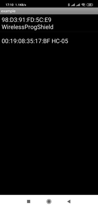
সেন্সরে লাগানো রাবার ব্যান্ডে আঙ্গুল প্রবেশ করিয়ে ‘Place finger on rubber band and start’ লেখা বাটনটি প্রেস করতে হবে।
/wp:paragraph wp:image {“id”:77935,”sizeSlug”:”large”}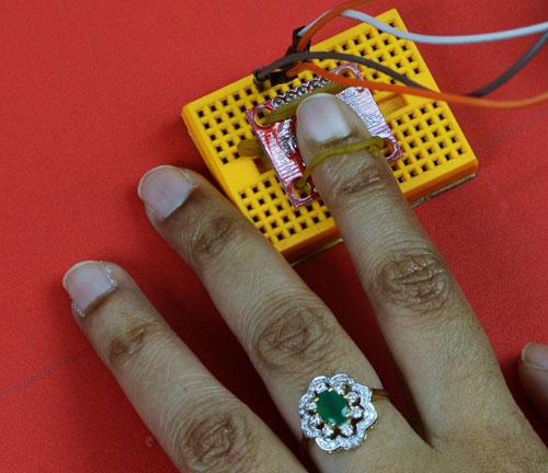
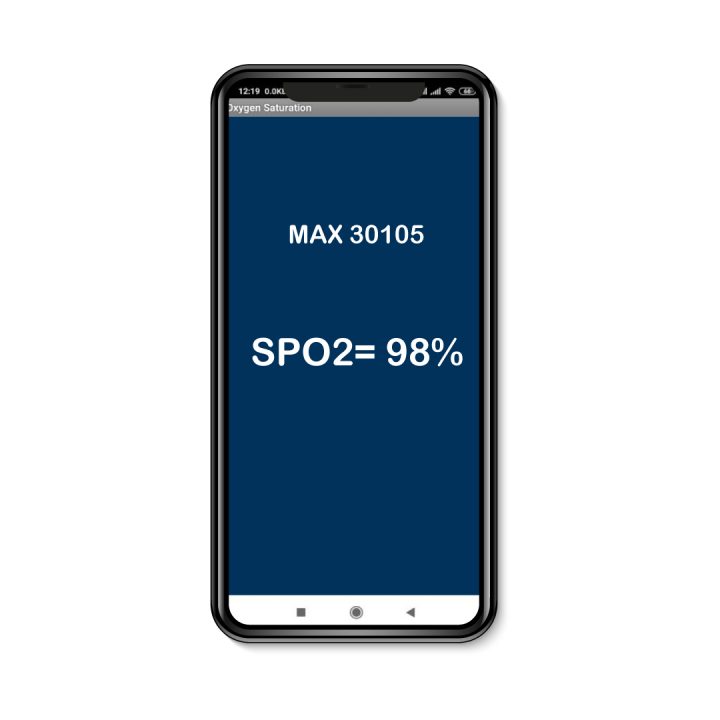
তারপর এভাবেই মোবাইলের স্ক্রিনে অক্সিজেন স্যাচুরেশনের পরিমাণ দেখা যাবে।
/wp:paragraph wp:image {“id”:77926,”sizeSlug”:”large”}
/wp:paragraph ]]>